Common biogas plant types can be differentiated according to methods of substrate feed, biogas collecting methods, materials used for their construction, horizontal or vertical digester position, underground and above-ground digester location and according to additional equipment used.
Substrate feed methods

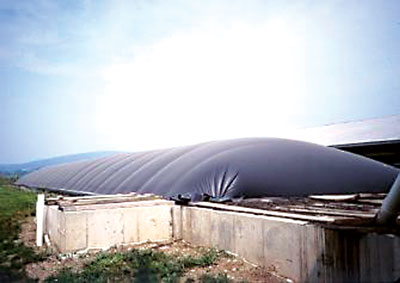
Figure 10. Balloon plant in Sri Lanka.Source: SNV Reference Guide on Climate Change and Rural Energy, 2004,
http://www.snvworld.org/cds/rgccre/ClimateChange_RuralEnergy.htm.
According to substrate upload method 2 types of biogas plants can be distinguished:
Batch biogas plants are loaded with substrate completely and after some determined digestion time are fully unloaded. For this loading method any design of biogas plant and any type of substrate can be used, but such plants are distinguished by unstable biogas production.
Continuous load types are loaded with relatively small daily portions of substrate. At the time of loading of the new substrate equal portion of digested slurry is unloaded. Substrate for this type of plants should be liquid and homogenous. Biogas production is stable and quantitatively exceeds the volume of biogas produced with batch plants. Almost all biogas plants built today in developed countries are continuous type plants.
Biogas collection methods

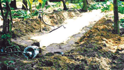
Figure 11. Canal biogas plant.
Source:«Biomass Energy Systems», ACRE,
the Australian CRS for Renewable Energy Ltd,
http://wwwphys.murdoch.edu.au/acre/.
The appearance of biogas plants depends on the chosen biogas collection method. Balloon plant consists of a digester bag (e.g. PVC) in the upper part of which the gas is stored. The inlet and outlet are attached directly to the plastic skin of the balloon. The gas pressure is achieved through the elasticity of the balloon and by added weights placed on the balloon. Advantages are low cost, ease of transportation, low construction sophistication, high digester temperatures, uncomplicated cleaning, emptying and maintenance.
Among disadvantages of balloon plants are high damage susceptibility, short exploitation period (2-5 years), and low capacity of creating additional employment. [8].
A variation of the balloon plant is channel-type digester, which is usually covered with plastic sheeting and a sunshade. Such plants are often used in developed countries, especially for waste water utilization. Balloon plants can be recommended wherever the balloon skin is not likely to be damaged and where the temperature is even and high.
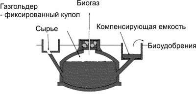
Fixed-dome plants consist of a fixed dome-shaped digester. Gas is collected in the upper [part of the digester. When a new portion of substrate is loaded, the slurry is displaced into the compensation tank. Gas pressure increases with the volume of gas stored and the height difference between the slurry level in the digester and the slurry level in the compensation tank.
Chinese fixed-dome plants (see Figure 12) are an archetype for all such plants. More than 12 million such plants have been constructed and is functioning in China [24]. Biogas pressure is unstable and usage of gas in household appliances is therefore difficult.
However, utilization of the gas is less effective as the gas pressure fluctuates substantially. Burners and other simple appliances cannot be set in an optimal way. If the gas is required at constant pressure it is recommended to install pressure regulator in digester of choose a different design of biogas plant [8].
Digesters of fixed-dome plants are usually masonry structures, structures of cement and ferro-cement exist. Fixed-dome plants must be covered with earth up to the top of the gas-filled space to counteract the internal pressure (up to 0,15 bar). Due to economic parameters, the recommended minimum size of a fixed-dome plant is 5 m3. Digester volumes up to 200 m3 are known and possible.

Figure 12. Fixed-dome plant.
Source: AT Information: Biogas, GTZ project Information and Advisory Service on Appropriate Technology (ISAT), Eshborn, Deutschland, 1996
Gas holder – the top part of a fixed-dome plant (the gas space) must be gas-tight. Concrete, masonry and cement rendering are not gas-tight. The gas space must therefore be painted with a gas-tight layer (e.g. Latex or synthetic paints). A possibility to reduce the risk of cracking of the gas-holder consists in the construction of a weak-ring in the masonry of the digester. This “ring” is a flexible joint between the lower (water-proof) and the upper (gas-proof) part of the hemispherical structure. It prevents cracks that develop due to the hydrostatic pressure in the lower parts to move into the upper parts of the gas-holder.

Figure 13. Floating-drum plant in Sadovoe village,
Litinsky rayon, Vinnitskaya Oblast, Ukraine.
Source: SFG «TERRA» http://www.is.svitonline.com/teppa/
Floating-drum plants consist of an underground digester and a moving gas-holder. The gasholder floats either directly on the fermentation slurry or in a water jacket of its own. The gas is collected in the gas drum, which rises or moves down, according to the amount of gas stored. The gas drum is prevented from tilting by a guiding frame. If the drum floats in a water jacket, it cannot get stuck, even in substrate with high solid content.
Advantages are the simple, easily understood operation – the volume of stored gas is directly visible. The gas pressure is constant, determined by the weight of the gas holder. The construction is relatively easy, construction mistakes do not lead to major problems in operation and gas yield. Disadvantages are high material costs of the steel drum, the susceptibility of steel parts to corrosion. Because of this, floating drum plants have a shorter life span than fixed-dome plants and regular maintenance costs for the painting of the drum [8].

Figure 14. Indian standard for constructing floating-drum plant.
Source: AT Information: Biogas, GTZ project Information and Advisory
Service on Appropriate Technology (ISAT), Eshborn, Deutschland, 1996
In the past, floating-drum plants were mainly built in India. A floating-drum plant consists of a cylindrical or dome shaped digester and a moving, floating gas-holder, or drum.
The gas-holder floats either directly in the fermenting slurry or in a separate water jacket. The drum in which the biogas collects has an internal and/or external guide frame that provides stability and keeps the drum upright. If biogas is produced, the drum moves up, if gas is consumed, the gasholder
sinks back. Floating-drum plants are used chiefly for digesting animal and human feces on a continuous feed mode of operation, i.e. with daily input. They are used most frequently by small- to middle-sized farms (digester size: 5-15m3) or in institutions and larger agro-industrial estates
(digester size: 20-100m3).
Horizontal and vertical biogas plants
The choice of digester placement depends on upload substrate method and availability of free space on the territory of the farm. Horizontal digesters are well suited for continuous type plants and under the condition of sufficient space. Vertical digesters are more suited for batch feed types of plants and are used when the space that can be allocated to biogas plant is limited.
Underground and above-ground plants
When choosing place for biogas plant it is necessary to take into account the topography and use it for optimization of plant’s function. For example, it is very convenient to place biogas plant on the hillside so that inlet is situated low enough and substrate in digester moves on account of light inclination to outlet that would be elevated for convenience of loading the fertilizer to vehicles.
Another factor that has to be considered when choosing between underground and surface plants is better heat insulation of underground plants and insignificant influence of daily changes in ambient temperature as the temperature on the level below 1 meter underground is virtually constant [8].
Steel, concrete and masonry digesters [8,19]

Figure 15. Biogas plant, placed on a hillside.
Plants can be also distinguished by the materials used for digester construction. Concrete digesters are normally constructed underground. Concrete digester has cylindrical shape and small plants (up to 6 m3) can be mass produced. However special measures for digester encapsulation are necessary. Advantages: low construction costs and materials, possibility of mass production.
Disadvantages: Substantial consumption of essentially good-quality cement; workmanship must meet high quality standards; uses substantial amounts of expensive wire mesh; special sealing measures for the gas-holder are necessary.
Masonry digesters are constructed for underground plants with fixed or floating gas holder and have rounded form. Advantages: low initial investment and long useful life, absence of moving or susceptible to corrosion parts, compact construction, takes up little space and is well insulated, construction created local employment. Underground placement allows to limit the area taken up by the plant and protects digester from sudden temperature changes. Disadvantages:

Figure 16. Masonry digester construction in Cuba.
Source: V. Nekrasov «Microbiological anaerobic
biomass conversion», unpublished, 2002.
Masonry digester requires special sealing measures for ensuring impermeability and highly qualified personnel, gas leaks are common. Functioning of the plant is impeded by the underground placement, plant requires thorough calculation of the construction levels, substrate heating in digester is very difficult and expensive. Therefore, masonry digesters can be recommended for use in warm countries and with availability of qualified personnel.
Steel digesters are inherently gas-tight, have good tensile strength, and are relatively easy to construct. In many cases, a discarded steel vessel of appropriate shape and size can be salvaged for use as a biogas digester. Susceptibility to corrosion both outside (atmospheric humidity) and inside (aggressive media) can be a severe problem. As a rule, some type of anticorrosive coating must be applied and checked at regular intervals. Steel vessels are only cost-effective, if second-hand vessels (e.g. train or truck tankers) can be used.
Additional equipment
As an example of use of additional equipment typical for developed countries biogas plant will be considered. Mixing pit varies in size and shape according to the nature of substrate. It is equipped with propellers for mixing and/or chopping the substrate and often with a pump to transport the substrate into the digester. At times, the substrate is also pre-heated in the mixing pit in order to avoid a temperature shock inside the digester.

Figure 17. Typical for developed countries biogas plant with flexible gas holder.
Source: AT Information: Biogas, GTZ project Information and Advisory Service on Appropriate Technology (ISAT), Eshborn, Deutschland, 1996
Fermenter or digester is insulated and made of concrete or steel. To optimize the flow of substrate, large digesters have a longish channel form. Large digesters are almost always agitated by slow rotating paddles or rotors or by injected biogas. Co-fermenters have two or more separated fermenters. The gas can be collected inside the digester, then usually with a flexible cover.
The digester can also be filled completely and the gas stored in a separate gas-holder.
Gas-holder is usually of flexible material, therefore to be protected against weather. It can be placed either directly above the substrate, then it acts like a balloon plant, or in a separate ’gas-bag’. Separate steel gas holder are also used.
Slurry store is used for storage of slurry during winter. The store can be open (like conventional
open liquid manure storage) or closed and connected to the gas-holder to capture remaining gas production. Normally, the store is not heated and only agitated before the slurry is spread on the field.
Gas use element is normally a thermo-power unit which produces electricity for the farm, the grid and heat for the house, greenhouses and other uses.
